New Solutions for Low-Volume, High-Mix Automation
By Louis Dicaire and Ian McLaren Louis Dicaire is vice president of Marketing, AGT Robotics, and Ian McLaren is global product manager Robotics Automation, ESAB (esabna.com), United Kingdom. Reprinted with permission: The AWS Welding Journal Recent advances in software, vision systems, and 3D laser scanning now combine to enable what was previously impossible: profitable automated solutions for welding, cutting, gouging, and grinding in low-volume, high-mix applications. Using self-learning robotic technology, unique parts that took 25 or more hours to fabricate now take 45 min. By reducing cost per part and enhancing long-term cash flow, companies that once fabricated parts overseas are reshoring their work and simultaneously growing domestic employment by winning more contracts. Good candidates for self-learning robotic applications include those that have a notion of family in their components. Structural steel I-beams provide a prime example. A typical beam will have a W section (main beam), a start plate and an end plate, a few stiffeners, and some connector plates. With just a few common parts, their dimensions can be adjusted to build an infinite number of I-beams that satisfy any need. Previously, structural steel building and bridge components would be entirely welded by an operator using a combination of gas metal arc welding (GMAW) for tacking and flux cored arc welding (FCAW) for the primary welds. Now, self-learning robotic technology can easily weld such parts.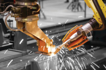
The next generation of low-volume, high-mix automation welding stations can also include automatic positioning of components, such as this clip.
- Shifting to the next smallest wire diameter while maintaining a similar wire feed speed and slightly reducing voltage. Using a smaller wire increases current density, which in turn enables an increase in travel speed and deposition rates while reducing heat input.
- Shifting from solid to tubular wires, typically a metal cored wire. Metal cored wires can better compensate for gaps, catch both sides of the plate and provide good tie-in at the toes of the weld. In addition, they often reduce spatter issues to minimize postweld cleanup, and they tolerate mill scale much better.
- Shifting to a high-speed welding process, often a modified spray transfer process. As noted above, these processes can weld at or in excess of 50 in./min. A human welder simply cannot move at this speed for an eight-hour shift and maintain consistent quality.