Brazing 101: Induction Heating
The basics of induction brazing are provided to dispel common misconceptions
BY W. ADAM MORRISON
W. ADAM MORRISON (amorrison@ ajaxtocco.com) is the low-power products manager at Ajax TOCCO Magnethermic Corp., Warren, Ohio.
Reprinted with permission: The AWS Welding Journal
This article is based on a presentation at the 7th International Brazing and Soldering Conference (IBSC) held April 15–18, 2018, in New Orleans, La.
Induction heating is a well-established heating method that many still consider new technology. Although induction heating technology is approaching 100 years of commercialization, questions and misconceptions surrounding its application still exist. For example, one common misunderstanding is that induction heating will only heat magnetic components. However, induction heating can be used to heat any electrically conductive material.
It is also important to consider both brazing and induction heating as separate and different processes to understand and apply them. Brazing is a joining process, while induction heating is a heating process that is often used as a single step of the brazing process.
Numerous texts and studies have been published about brazing and other metal-joining techniques. It is not the intent of this paper to present all the details associated with brazing processes. Instead, general rules of thumb will be presented for a detailed discussion on induction heating technology. This article also addresses common misconceptions of induction heating in relation to its brazing-related applications.
Induction Heating Defined
Induction heating is a thermal process in which an electrically conductive material is placed within a varying magnetic field and heated via hysteresis (magnetic materials only) and/or induced electrical current (all conductive materials). The changing magnetic field is generated by an alternating current (AC) being passed through an electrical winding (coil/inductor). Induction heating is a noncontact heating method that is extremely fast and efficient when compared to other heating technologies used for brazing.
Hysteresis Heating
Induction heating can heat any electrically conductive material, magnetic and nonmagnetic. There is one key difference associated when heating a magnetic part vs. a nonmagnetic part. Magnetic parts, such as iron, have magnetic particles within their atomic structure called domains. These domains are like small bar magnets. The domains physically align themselves with the polarity of the magnetic field applied to the part. As the magnetic field reverses, the domains physically reverse direction. This constant reversing of direction results in internal friction heating. This heating through magnetic domain switching is known as hysteresis heating. Hysteresis only occurs in magnetic materials and is the most efficient form of induction heating. It can also exceed 90% efficiency.
Eddy Current Heating
When sufficiently heated, magnetic materials will lose their magnetism. This is called the Curie point (typically around 1400°F for iron). Once a magnetic part reaches its Curie point, hysteresis heating stops. Without proper frequency and/or power selection, the heating will stall at approximately 1400°F. This is one reason some novices believe induction heating will not heat above 1400°F. With proper frequency and power selection, it is possible to heat to any temperature up to several thousand degrees.
The heating that takes place beyond the Curie point or in nonmagnetic materials is eddy current heating. This type of energy transfer is the same as what takes place inside electrical transformers. The heating inductor is the primary of the transformer circuit, and the heated part is the secondary winding. The heat produced is known as “I squared R losses” (P = I2R), derived from Ohm’s law (V = I*R).
Eddy current heating is what allows electromagnetic induction to heat any electrically conductive material, including gold, copper, silver, aluminum, and many others. The efficiency of eddy current heating will vary depending on the alloy being heated from 50% to as low as 5% conversion efficiency. The term electrical eddy current is derived from the description of small surface currents that can be seen within larger flows of water, such as streams and rivers. In much the same way, induced electrical eddy currents only circulate on the surface of the part.
Reference Depth of Heating
The higher the frequency of operation (Hz), the shallower the eddy currents are. The depth at which the current penetrates the surface is called the reference depth and represents the depth at which 63% of the induced current is flowing. Most induction heating systems for brazing operate between 10 and 50 kHz. Depending on magnetic permeability and material resistivity, the reference depth of heating can vary between 0.01 and 0.20 in. (0.2 and 5 mm) within this frequency range.
It’s important to consider depth of heating when choosing an induction heating system. If the depth is excessive, very little heating will occur due to cancellation of eddy currents. Cancellation occurs when eddy currents from opposing sides of the part encounter each other. As a rule, the depth of current should be no greater than one-half the thickness and/or diameter of the part being heated.
Although frequency of operation is the primary influencer of heating depth, so too is the electrical resistivity of the part being heated and its magnetic permeability. The formula for calculating reference depth is D = 3160*√(ρ/μf), where ρ is the electrical resistivity of the material being heated in micro-ohm inches; μ is the relative magnetic permeability in Henrys/meter; and f is the frequency of operation in hertz. The formula shows that the depth of heating increases as the electrical resistivity increases. Conversely, the depth decreases as the magnetic permeability or operating frequency increases.
Magnetic permeability is the ability of a material to absorb and retain magnetic flux. The greater the ability to retain flux, the higher the permeability. Nonmagnetic materials have a permeability of 1, while a good magnetic material like iron has a permeability of 5000. Carbon steel has a relative magnetic permeability of 100. It is important to consider the permeability at the brazing temperature due to the Curie point of some materials. Remember that steel loses magnetism at approximately 1400°F, at which point its permeability changes from 100 to 1. This would result in a 10× increase in the depth of current penetration at temperatures above the Curie point. If the wrong frequency is selected, then heating will stall at the Curie point.
The laws of thermal dynamics are not avoided with induction heating. The heat generated within the part is not limited to the depth of current penetration. The depth of heating will increase via conduction. The additional depth of heating resulting from soak/heat time can be approximated by the formula D = √0.0015t, where D is the depth in inches, and t is the time in seconds.
Due to the tendency of AC to collect on the surface of a part, it is possible to select a frequency that is too high. An operating frequency that is too high will cause the current to collect in corners of parts, such as the corners of a hex nut assembly. This will create localized hot spots that could melt the base metal before the filler metal melts. Frequency optimizes efficiency, but it is power that gets the work done.
Power Requirements
Power is the amount the energy transferred over time. Most induction heaters are rated by their ability to deliver power, typically rated in kilowatts (kW). Power offerings for induction heating power supplies vary widely. Industrial grade induction power supplies can be found from as low as 1 kW to more than 20 MW (1000 to 20,000,000 W). For brazing applications, most brazing processes fall within the 5 to 50 kW range, but several hundred kWs for larger applications are not uncommon.
Selecting the proper kW rating is as important as proper frequency selection. A kW rating that is too low will lack the power to achieve the brazing temperature, take too long to braze, and have an excessive heat-affected zone (HAZ). A kW rating that is too large will lack the necessary resolution for stable process control, overheat parts, and is a waste of capital resources to acquire and maintain.
There are several factors in determining the required power for a brazing process. Allowed heat time, target temperature, starting temperature, heated mass, and base metal alloy are the primary factors. Heat time should be sufficient for the flux to become active, and for the alloy to flow into the joint via capillary action. Excessive heat times should be avoided due to the limited active life of a heated flux. Also, longer heat times allow for increased formation of oxides while the part is at elevated temperatures.
Base metals vary in density, specific heat, electrical resistivity, and relative magnetic permeability as well as other defining characteristics, but these four traits are the most important for calculating power requirements for a process.
As an example, consider two parts of equal-heated mass, one made from iron and one from copper. Copper is one of the most difficult materials to heat with induction in terms of efficiency, while iron is one of the easiest. Induction heating efficiency when heating copper is typically 15%, while iron is greater than 90%. To achieve the same temperature in the same time for the two parts, five times as much power would be required for the copper part. The difference in electrical resistivity and magnetic permeability are the main reasons for the differences in power requirements. The lower resistivity of copper requires significantly more current to generate the same I-squared-R losses as iron. Iron also benefits from the greater magnetic permeability, allowing it to be heated by hysteresis in addition to I-squared-R heating.
The following summarizes conversion efficiencies for common base metals heated with induction heating:
• Pure iron 95–98%
• Medium carbon steel 85–90%
• 316 stainless steel 45–50%
• Aluminum 35–40%
• Copper 5–15%.
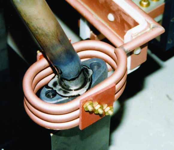
Heating Inductors
A heating inductor (coil) is an electrical winding in which AC is passed for generating an electromagnetic field with a specific pattern for heating an electrically conductive object.
When most people think of an induction heating coil (inductor), they envision a simple helical winding made from copper tubing that surrounds the part to be heated. Although this would be one form of an inductor, there are others to consider. Heating inductors can be made from hollow copper tubing, solid rod, flexible cable, and machined billet, as well as 3D printed from powdered copper alloys. The choice of inductor geometry is mostly determined by the process requirements. Copper is the chosen material for fabricating inductors due to its high electrical conductivity (low power losses), high thermal conductivity (easily cooled with water), and relatively low cost. Most inductors are water cooled due to reflected heat from the part and the amount of current flowing within the inductor (1000 A is typical).
The heating inductor is the most important component of an induction heating system. Inductors can be in many different configurations, such as solenoid, hair pin, pancake, transverse, inside diameter, channel, clamshell, and machined/3D-printed profile. Only the solenoid inductor surrounds the part.
It is a common misconception that the inductor must surround the part. However, an inductor can heat from the outside, the inside, one side, two sides, or three sides. Inductors are generally profiled to the shape of the part and/or the area of the part to be heated. The style of the inductor influences efficiency. For example, an internal heating inductor requires approximately two times as much power as a solenoid inductor. The joint clearance between the heated part and the inductor also influences efficiency. This is called the coupling joint clearance. As the coupling joint clearance increases, efficiency decreases.
It’s important an induction heating inductor expert be consulted early during the process development phase of an induction brazing process for the greatest chance of process success. A poorly designed inductor will use excessive power, have poor repeatability, require postworking of the parts, or may not work at all. The induction heating process is only as good as the inductor being used for the process.
Key design attributes of a quality inductor are as follows:
• Allows for easy insertion and removal of heated parts;
• Is compatible with the tooling holding the heated parts;
• Has adequate copper size to accommodate the kW rating of the induction heater;
• Provides uniform heating of the braze joint area;
• Retains its shape and position during use;
• Properly insulated to protect from contamination and accidental contact with the parts being heated;
• Low inductance leads for efficient power transfer; and
• Properly documented for duplication.
Process Controls and FEA
Modern day controls can be integrated throughout the induction brazing process for accuracy and consistency. Modern induction heating systems employ numerous microprocessors and can provide data about the performance characteristics of a process. Filler metal volume measurements (e.g., minimum/maximum temperatures, cooling rates, quench flows, energy delivery, etc.) are just a small sample of the data that can be collected. Further, this data is easily monitored from remote locations over corporate networks and the internet. Individual process data for completed parts can be stored for later review. Individual part processing and verification along with extreme repeatability are just a few of the hallmarks for induction heating for brazing applications.
Using finite elemental analysis (FEA) software and proprietary simulation software packages, induction original equipment manufacturers can accurately predict heat patterns, temperature rises, temperature distribution, stress, strain, and even metallurgical changes in parts before a single part is physically heated.
It is easy to see that induction heating offers benefits over other heating methods, including precision, speed, control, and energy efficiency. However, induction heating is just one portion of a brazing process. Despite the heat control afforded by electromagnetic induction, the brazing process will only be as accurate and repeatable as the ability to control the other variables of the brazing process, such as part tolerance, part location, part cleanliness, consistent flux application, and filler metal.
Flux and Fluxless Brazing
Parts should be thoroughly cleaned prior to heating to maximize alloying of the base and filler metals. The cleaned parts should be protected from oxidation during the heating process using a chemical flux or a controlled atmosphere environment. Electromagnetic induction is compatible with both traditional chemical flux and controlled atmosphere brazing applications. Carbide cutting tools often use traditional mineral fluxes and silver-bearing filler metals, while high-pressure automotive fuel rails often use a copper filler metal brazed within a vacuum or an inert atmosphere. Under no circumstances should a flux or reducing atmosphere be relied upon to compensate for poor part surface preparation prior to brazing.
Braze and Joint Design
It would be easy to oversimplify braze joint geometry. There are essentially only two styles of braze joint configurations: the butt joint and the lap joint. All other joints are variations of these two joint configurations. Joint design is influenced by intended use, type of filler metal, flux, and heating method. The main issue to consider regardless of the joint configuration is the joint and part geometry be consistent from part to part to have a repeatable process. Induction heating will deliver a consistent amount of heat to the part cycle to cycle, but variations in heat transfer and joint strength can arise from variations in joint consistency.
The joint clearance between the two parts will vary depending on the type of filler metal, flux, and thermal expansion of the parts. Joint clearances between components being joined can range from a slight interference fit to 0.010 in. For most induction brazing applications, the joint clearance will range from 0.002 to 0.005 in., which is the range for optimal joint strength. Smaller joint clearances and interference fits are acceptable for fluxless brazing applications, such as when brazing in an inert atmosphere using a copper filler metal.
Most induction heating processes use a fixed geometry inductor. The braze joint design should take in consideration the geometry of the heating inductor. The components should be able to be assembled within the inductor, and the finished brazement should be able to be removed from the inductor after brazing.
Part Fixture Design Considerations
Significant investment has been made in specifying the base metals, filler metal, flux, joint geometry, and heating method. Proper fixturing to hold the parts during the brazing process is also critical to the overall success of the process. Fixturing in relation to the use of induction heating for brazing processes should be nonmagnetic to minimize stray heating of the fixture.
Acceptable nonmagnetic materials would be 300 series stainless steel as well as aluminum. Stainless steel is heat, chemical, and wear resistant. It also has a relatively low thermal conductivity, and provides good toughness and wear resistance. Be sure to consider thermal expansion of the heated parts, during the brazing process, when designing a holding fixture.