Feedability: The Quintessential Problem with the GMAW of Aluminum
Learn what factors will prevent interruption in feeding aluminum welding wire BY THOMAS PFALLER, a process engineer at AlcoTec Wire Corp., Traverse City, Mich. This article is based on a presentation from the American Welding Society Aluminum Virtual Conference — Back to Basics held October 20 and 21, 2020. Reprinted with permission: The AWS Welding Journal Whenever discussions regarding the gas metal arc welding (GMAW) of aluminum arise, it is a safe bet that the topic will be centered on one of a handful of topics. Among these are filler selection, porosity, distortion, and feedability. While one might expect the first three items in that list to also be applicable to the GMAW of steel and stainless steel, feedability is one that aluminum seems to have exclusive discussion rights. The properties of aluminum welding wire make it particularly sensitive to the creation of shavings, microfines, and tangles within feeding systems. With the continued growth in the aluminum welding industry, more and more companies are dipping their toes into the ocean that is aluminum welding. Any production-minded manager or engineer should be sensitive to this topic because any interruption in the feeding of welding wire means a loss of productivity. The foundational knowledge relating to aluminum feedability can be segregated into the following points: wire quality, system considerations, and usage techniques. Each of these will be explored to ensure a comprehensive understanding of how to overcome the challenges of feeding aluminum welding wire. Alloys and Characteristics For anyone not intimately familiar with aluminum welding, a good baseline to start with is the differences in characteristics of aluminum filler wires. Within the aluminum welding world, the filler alloys are generally grouped into two families, each having relatively distinct features. The two families are hard wire and soft wire. The hard-wire alloys are the various 5xxx series alloys that are commercially available as filler alloys. Some common examples of these include 5356, 5183, 5554, and 5556. The two primary feedability characteristics of these alloys is that they are relatively stiff with good columnar strength. This makes the hard wires less prone to tangling but more susceptible to the formation of microfines. On the other hand, the soft-wire alloys include representatives from a few other alloy families: 1xxx, 2xxx, and 4xxx. A few of the common welding alloys include: 1100, 2319, 4043, and 4047. The soft-wire alloys have notably reduced columnar strength and are more prone to tangles anytime there is even a slight interruption in the feeding system. These wires also have a higher propensity to form shavings due to incorrectly configured equipment. These distinctions between hard- and soft-wire alloys will serve as a baseline for the following investigation into feeding aluminum wires. Types of Shavings During the explanation regarding the different aluminum alloys, two other foundational elements were mentioned: microfines and shavings. These terms are sometimes used interchangeably even though they identify two distinct failures within welding systems. Shavings are characterized by large chips or strands of aluminum, which are mainly the result of mechanical damage done to the wire — Fig. 1. Microfines, on the other hand, are much smaller particles similar to very coarse grain sand. These can come from mechanical damage from drive wheels but are commonly a function of the flaking surface of the hard-wire alloys. Once these fines start to build up in a feeding system, their propagation and accumulation increase significantly. As one might expect, both the shavings and micro-fines will cause interruptions in feeding. Understanding the differences between the appearance and causes can greatly assist in troubleshooting feedability issues.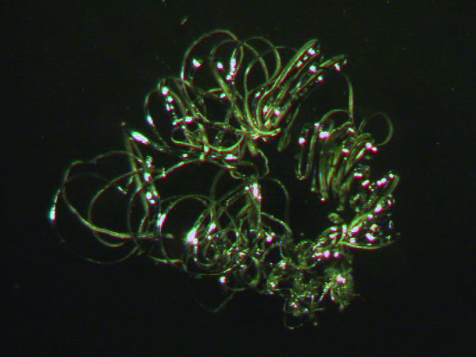 Manufacturing Quality
As with any process, if the starting material is of poor quality, a user can expect the end result to suffer. When looking at aluminum welding wire, there are a few attributes that help to ensure robust feedability. The first of these is level layer winding. This gives the user confidence that the wire has not become crossed on the spool. It also ensures that the wire is smooth and does not develop inconsistent bends that could interrupt feeding while passing through the contact tip.
One attribute that goes hand in hand with precision level layer winding is diameter tolerance. This comes from the fact that the process of precision winding aluminum wire is very sensitive to changes in wire diameter. A common tolerance that one might see in precision-wound wire is measured in ten-thousands of an inch. This is important for a welder because changes in wire diameter can affect the electrical connectivity of the wire in the contact tip. Loss of conductivity will result in either a burnback or arcing within the contact tip.
The final concern from a wire standpoint is the surface quality of the wire. Having aluminum wire with a smooth surface with good lubricity ensures that the wire will not hang up or snag in the feeding system. Unfortunately, even minute aluminum fines can build up and generate until feeding issues result. AlcoTec® Wire Corp. has developed a patented solution to this for the 5xxx products referred to as New Technology wire. This process ensures that the surface of the wire is slippery and free from the microfines that have traditionally wreaked havoc for aluminum welding machines across the globe. It is through the utilization of quality inputs that a process can have the best chance of producing a quality product with a high level of efficiency.
Welding Systems
When looking at the big picture of an aluminum welding system, we have addressed material attributes and wire manufacturing and quality. The next piece of the puzzle is the welding system itself. With a few exceptions, most welding machines are configured for welding with steel or stainless steel wire. This means that certain components may need to be checked to verify that they are optimal for the utilization of aluminum welding wire. There are a few key components to consider when moving aluminum wire from the spool to the welding torch.
The guides going in and out of the wire feeder should be made from a soft nonabrasive material. Common materials that work well are nylon/plastic guides. These keep the wire aligned while limiting abrasion on the soft surface of the aluminum wire. These guides should also be designed to limit the amount of open space available for the wire to be pushed into in the event of feeding issues. Drive wheels should be polished smooth to keep from galling the wire or peeling flecks off the surface of the wire. The most common geometry of drive wheels is polished U-groove. However, users may have success with other geometries given the wheels grip the wire without damaging the wire surface. The final element to be considered regarding drive wheels is that the pressure should be kept as low as possible. High drive roll pressure has a two-pronged damaging effect on the wire. The first is that excessive drive roll pressure can smash the softer alloys causing the wire geometry to be oval rather than round. When utilizing the harder 5xxx filler wires, excessive drive role pressure can result in the additional creation of microfines. Drive wheels should be cleaned periodically to remove any aluminum build up and to ensure that they “float” or self-align; thus, avoiding additional damage to the welding wire.
After the feeder, the wire travels through a liner to the welding torch. Like the guides, this liner should be a material that is soft to minimize abrasion on the wire. Common materials are nylon or nylon mixed with graphite. The length of the distance between the feeder and the torch is also important. When utilizing a push-only system, one can expect to have issues with a torch length greater than 12 ft (4 m). Quality push/pull type systems can successfully feed wire up to 30 ft (10 m).
The final component to consider for robust feedability is the contact tip. Contact tips have few attributes that often go overlooked in favor of buying based on sticker price, namely the quality of the copper alloy, size, geometry, and machining. The quality of the copper can ensure that the tip does not prematurely wear from the heat of welding and the thousands of feet of wire that pass through it. When considering size, the typical expectation is that the inside diameter of the contact tip should be approximately 10% oversized. Quality contact tip manufacturers will often figure this into their machining processes. Finally, if the manufacturers cut corners in their machining of the tips, burrs can be left behind. A common location to find machining burrs is at the inlet chamfer of the tip. This can affect the inside diameter of the tips and also shave the surface of the wire.
Tricks of the Trade
While the welding system configuration has an effect on the robustness of the aluminum wire feedability, the usage techniques also cannot be ignored. While the list could quickly get very exhaustive, here are a handful of things that many welders struggle against without even knowing it. First is keeping the liner from the feeder to the welding torch as straight as possible. Every loop and bend in the liner results in additional friction and the opportunity for fines to be created. The next item to consider is the importance of preventative maintenance on the equipment. Preventative maintenance (PM) can often be a challenge; however, it is important to make sure that the PM schedule makes sense and is effective. Depending on the welding shop, this could be as complex as a managed control plan or as simple as having the welder blow out the liner with compressed air at the beginning of a shift. Taking care of equipment will ensure that every time the welder initiates the welding arc feedability of the aluminum wire is not a concern. Finally, when handling full spools of aluminum welding wire, it is important to lift it from the center hub. If the spool is lifted by the flanges, the flanges may spread slightly, allowing the wire wraps in the corners to become pinched. This undoubtedly will cause feeding issues as the wire is paying off the spool during welding.
Summary
Welding is a complex activity with many nuanced components and theories to consider. As one small piece of the puzzle of the aluminum GMAW process, feedability is no exception. However, through the diligent consideration of the quality of the wire, equipment configuration, and usage techniques, a welder can keep his or her hood down satisfied at having overcome the quintessential problem relating to the GMAW of aluminum. This will ultimately lead to fewer production headaches and more production throughput.
Fig. 1 — Shavings are characterized by relatively long strands indicative of mechanical damage.
Manufacturing Quality
As with any process, if the starting material is of poor quality, a user can expect the end result to suffer. When looking at aluminum welding wire, there are a few attributes that help to ensure robust feedability. The first of these is level layer winding. This gives the user confidence that the wire has not become crossed on the spool. It also ensures that the wire is smooth and does not develop inconsistent bends that could interrupt feeding while passing through the contact tip.
One attribute that goes hand in hand with precision level layer winding is diameter tolerance. This comes from the fact that the process of precision winding aluminum wire is very sensitive to changes in wire diameter. A common tolerance that one might see in precision-wound wire is measured in ten-thousands of an inch. This is important for a welder because changes in wire diameter can affect the electrical connectivity of the wire in the contact tip. Loss of conductivity will result in either a burnback or arcing within the contact tip.
The final concern from a wire standpoint is the surface quality of the wire. Having aluminum wire with a smooth surface with good lubricity ensures that the wire will not hang up or snag in the feeding system. Unfortunately, even minute aluminum fines can build up and generate until feeding issues result. AlcoTec® Wire Corp. has developed a patented solution to this for the 5xxx products referred to as New Technology wire. This process ensures that the surface of the wire is slippery and free from the microfines that have traditionally wreaked havoc for aluminum welding machines across the globe. It is through the utilization of quality inputs that a process can have the best chance of producing a quality product with a high level of efficiency.
Welding Systems
When looking at the big picture of an aluminum welding system, we have addressed material attributes and wire manufacturing and quality. The next piece of the puzzle is the welding system itself. With a few exceptions, most welding machines are configured for welding with steel or stainless steel wire. This means that certain components may need to be checked to verify that they are optimal for the utilization of aluminum welding wire. There are a few key components to consider when moving aluminum wire from the spool to the welding torch.
The guides going in and out of the wire feeder should be made from a soft nonabrasive material. Common materials that work well are nylon/plastic guides. These keep the wire aligned while limiting abrasion on the soft surface of the aluminum wire. These guides should also be designed to limit the amount of open space available for the wire to be pushed into in the event of feeding issues. Drive wheels should be polished smooth to keep from galling the wire or peeling flecks off the surface of the wire. The most common geometry of drive wheels is polished U-groove. However, users may have success with other geometries given the wheels grip the wire without damaging the wire surface. The final element to be considered regarding drive wheels is that the pressure should be kept as low as possible. High drive roll pressure has a two-pronged damaging effect on the wire. The first is that excessive drive roll pressure can smash the softer alloys causing the wire geometry to be oval rather than round. When utilizing the harder 5xxx filler wires, excessive drive role pressure can result in the additional creation of microfines. Drive wheels should be cleaned periodically to remove any aluminum build up and to ensure that they “float” or self-align; thus, avoiding additional damage to the welding wire.
After the feeder, the wire travels through a liner to the welding torch. Like the guides, this liner should be a material that is soft to minimize abrasion on the wire. Common materials are nylon or nylon mixed with graphite. The length of the distance between the feeder and the torch is also important. When utilizing a push-only system, one can expect to have issues with a torch length greater than 12 ft (4 m). Quality push/pull type systems can successfully feed wire up to 30 ft (10 m).
The final component to consider for robust feedability is the contact tip. Contact tips have few attributes that often go overlooked in favor of buying based on sticker price, namely the quality of the copper alloy, size, geometry, and machining. The quality of the copper can ensure that the tip does not prematurely wear from the heat of welding and the thousands of feet of wire that pass through it. When considering size, the typical expectation is that the inside diameter of the contact tip should be approximately 10% oversized. Quality contact tip manufacturers will often figure this into their machining processes. Finally, if the manufacturers cut corners in their machining of the tips, burrs can be left behind. A common location to find machining burrs is at the inlet chamfer of the tip. This can affect the inside diameter of the tips and also shave the surface of the wire.
Tricks of the Trade
While the welding system configuration has an effect on the robustness of the aluminum wire feedability, the usage techniques also cannot be ignored. While the list could quickly get very exhaustive, here are a handful of things that many welders struggle against without even knowing it. First is keeping the liner from the feeder to the welding torch as straight as possible. Every loop and bend in the liner results in additional friction and the opportunity for fines to be created. The next item to consider is the importance of preventative maintenance on the equipment. Preventative maintenance (PM) can often be a challenge; however, it is important to make sure that the PM schedule makes sense and is effective. Depending on the welding shop, this could be as complex as a managed control plan or as simple as having the welder blow out the liner with compressed air at the beginning of a shift. Taking care of equipment will ensure that every time the welder initiates the welding arc feedability of the aluminum wire is not a concern. Finally, when handling full spools of aluminum welding wire, it is important to lift it from the center hub. If the spool is lifted by the flanges, the flanges may spread slightly, allowing the wire wraps in the corners to become pinched. This undoubtedly will cause feeding issues as the wire is paying off the spool during welding.
Summary
Welding is a complex activity with many nuanced components and theories to consider. As one small piece of the puzzle of the aluminum GMAW process, feedability is no exception. However, through the diligent consideration of the quality of the wire, equipment configuration, and usage techniques, a welder can keep his or her hood down satisfied at having overcome the quintessential problem relating to the GMAW of aluminum. This will ultimately lead to fewer production headaches and more production throughput.
Fig. 1 — Shavings are characterized by relatively long strands indicative of mechanical damage.